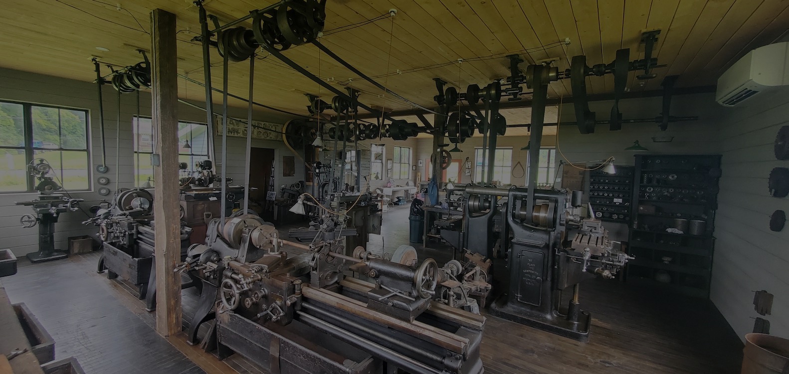
NOTABLE ARTIFACTS OF THE MUSEUM featured throughout the Machine Shop
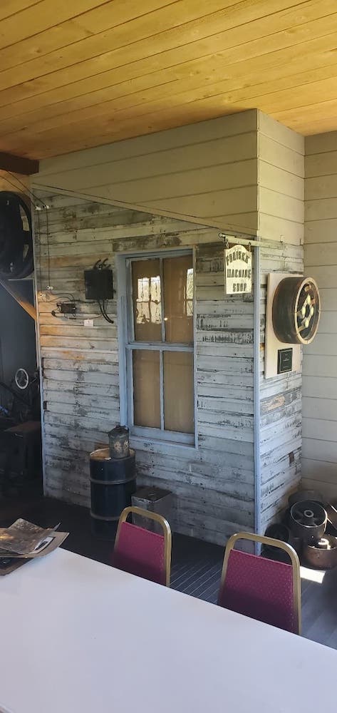
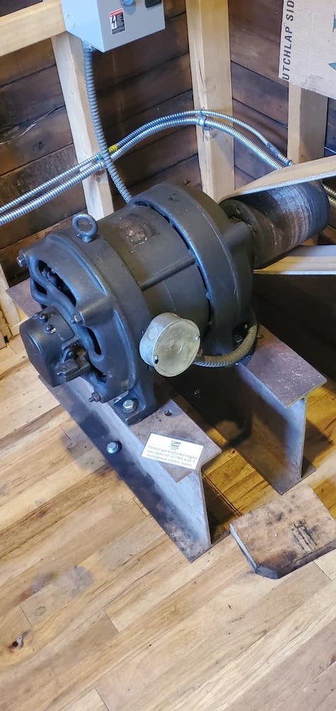
The engine room was originally outside the shop, only being incorporated as seen here when the 1930’s addition was built. This engine room is replicated by using the original siding and window removed from the Davenport Shop on West College Street. The engine room contained a four-cylinder natural gas powered engine which was constantly rebuilt for continuous service by the apprentices working in the shop. It was replaced in the 1960’s by the five-horsepower electric motor in use today.
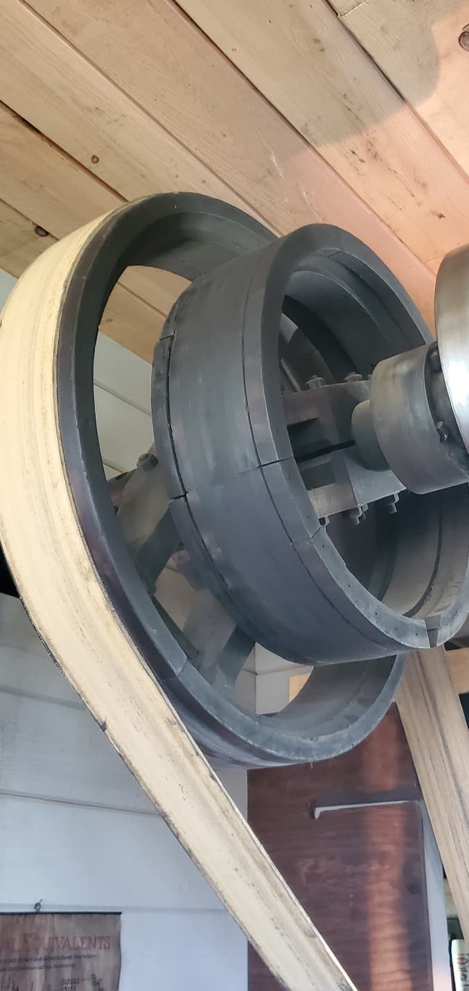
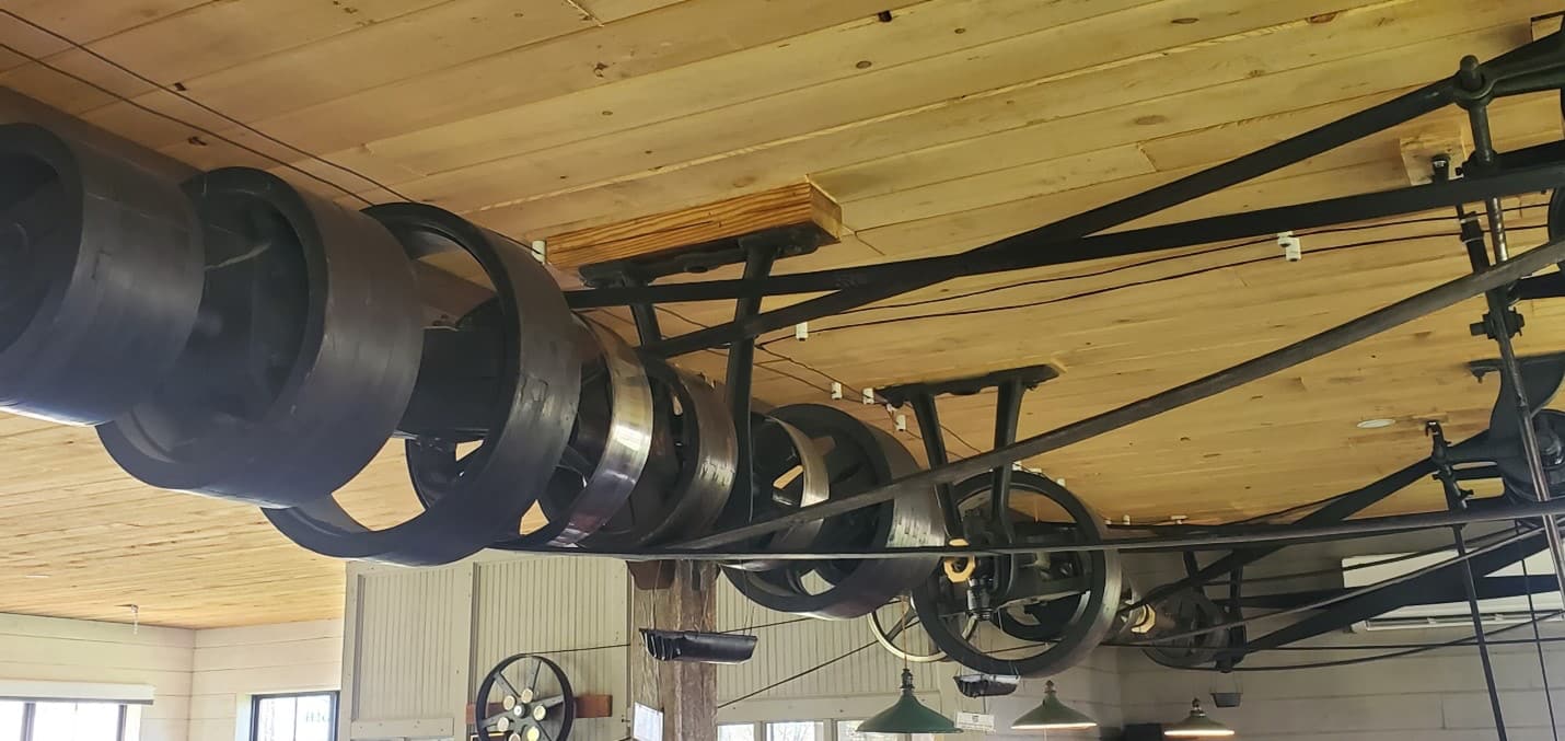
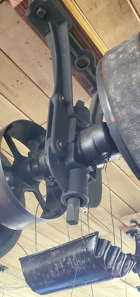
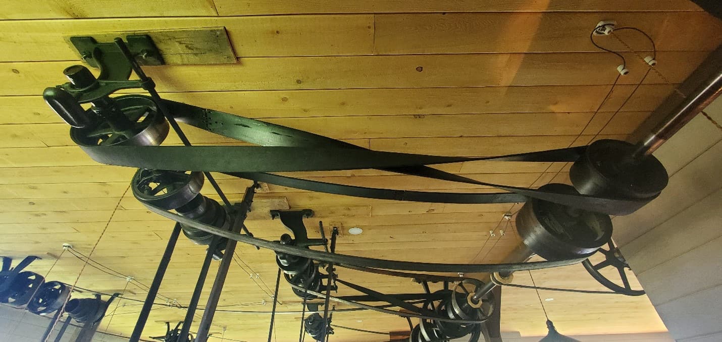
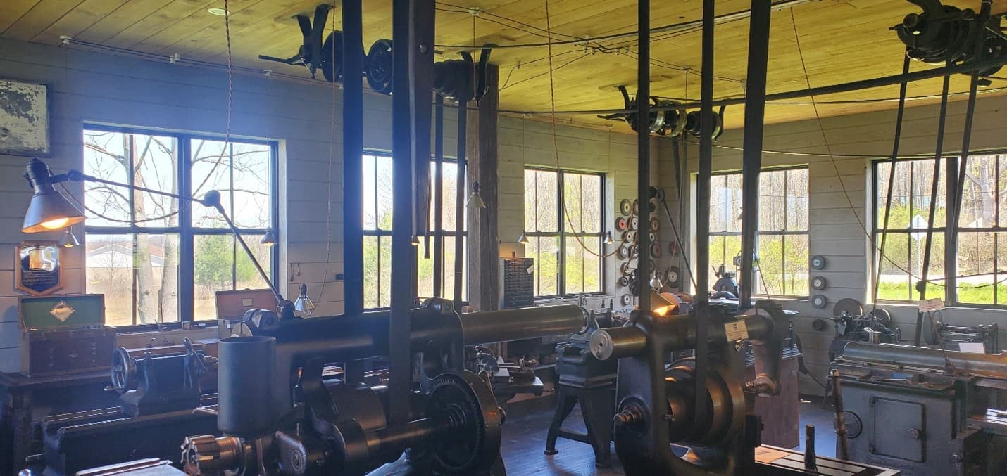
The main overhead Line Shaft is two-inch diameter and thirty feet long (in two pieces). It is powered by a motor located in the engine room and driven by a five-inch belt coming onto a thirty-two-inch wooden pully in the main shop and turns the line shaft at about 200 RPM’s. The shaft is supported by five support arms each containing a two piece babbitt bearing which has oil cups on top with wool wicks inside. The oil cups need to be filled daily and each has a drip pan underneath to control the drips. Two of these babbitt bearing housings also include mechanical oil throw rings inside them to assure adequate oil flow onto the shaft.
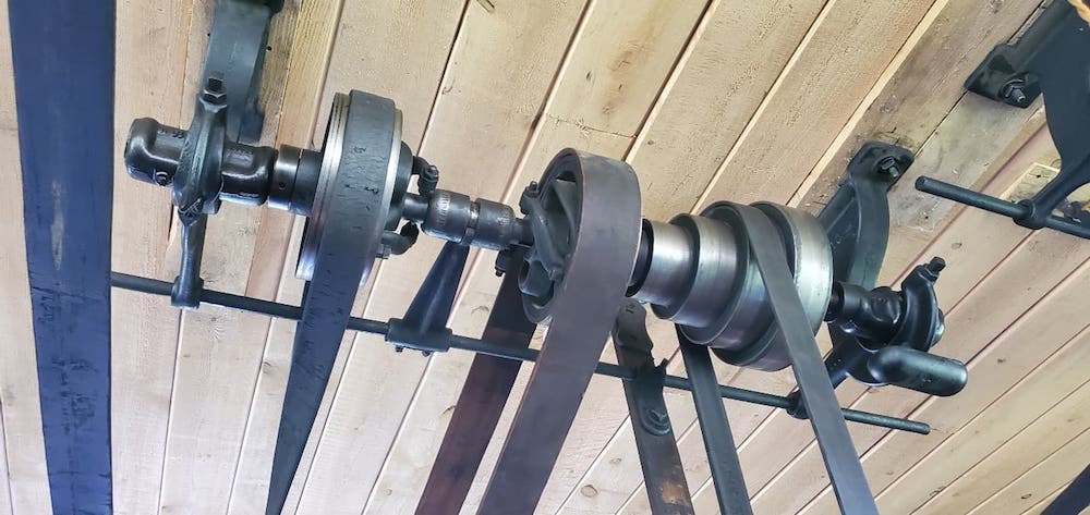
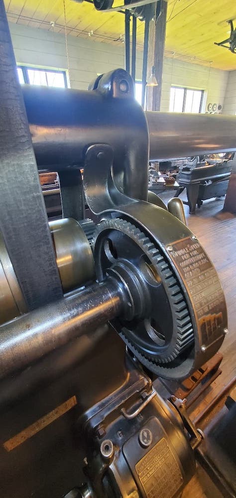
The line shaft is started each day and runs continuously, and of course only at one speed and in one direction. Each machine tool is powered by an individual common shaft located above which contains a clutch with a belt running to the main line shaft which allows each operator to start and stop his machine as desired. To achieve the reverse direction most machines require, two clutches are put on the common shaft with a belt on each, but one of the belts is crossed so the common shaft pulley rotates in the opposite direction so the machine operator can switch to reverse by switching to the second clutch. The basic speed of the machine is determined by the diameter of the pulley on the main shaft, and the operator moves the machine tool’s leather belt up or down the step pulleys to get his preferred speed. Some machines also have a “back” gear which enables four more speeds when you use the reverse pulley clutch.
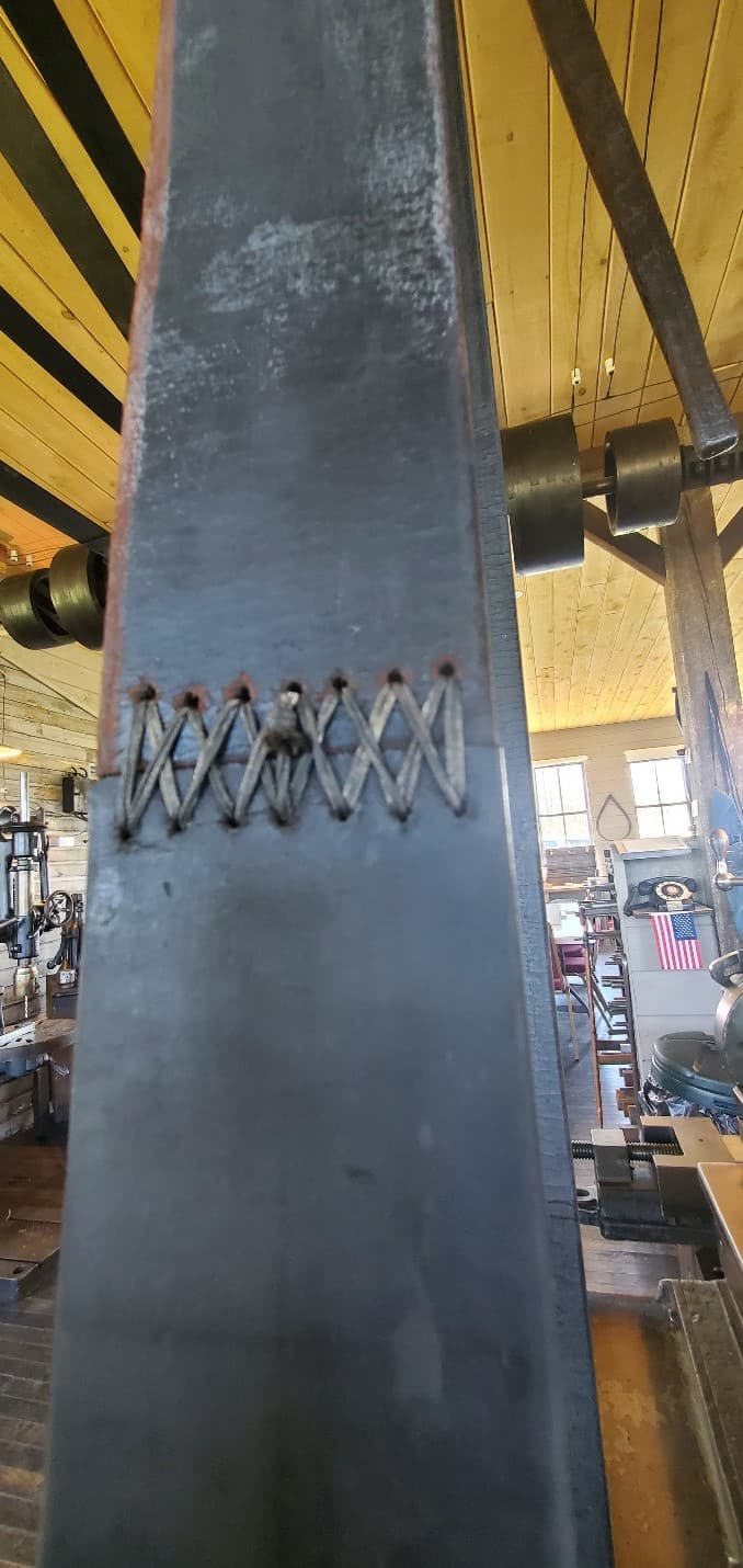
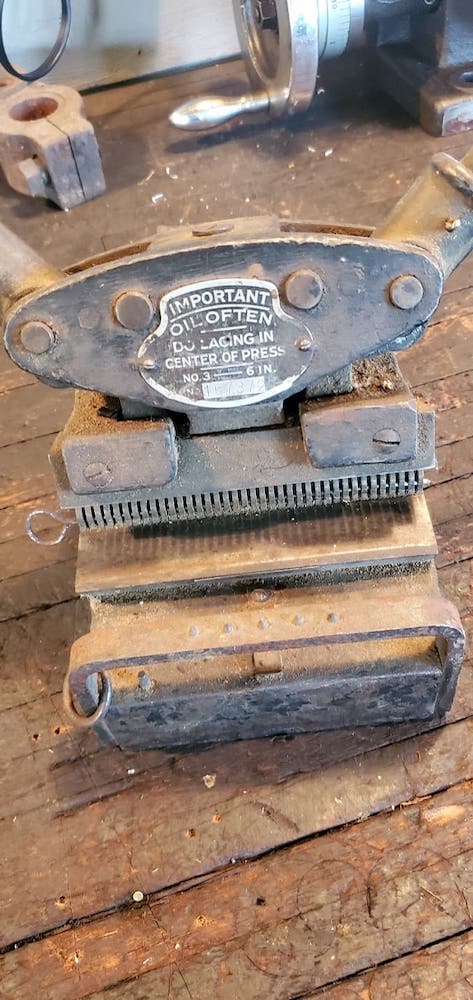
The leather belts used on the pulleys are intended to be kept clean and oil free for the best traction on the pulleys. Some of the pulleys are steel (the shiny ones), but most are made of wood. The pulleys do have a ‘crowned’ running surface to help keep the belts centered. As a ‘rule of thumb’, one inch of belt width is required to achieve one horsepower of energy at the driven pulley. Each individual belt must be maintained at the appropriate length since the weight of the belt sag and tension of the belt between the pulleys achieves the desired horsepower as well as keeping the belts on track. The proper belt length is achieved by cutting the belt ends square, punching stitch holes, carving thread grooves on the inside so the threads lay flush, and sewing the ends together keeping straight stiches on the running side and all the crossing stitches and knots on the outside. This hand stitching is important on the power belt running from the common shaft down to each machine as the operator moves these belts up and down the step pulleys by pushing on them by hand while they are running. A mechanical metal stitch plate would certainly injure the operator. On display is a belt stitching tool used for applying metal stitch plates, like the one used on the five-inch engine room belt (the only metal stitch in the building). The engine room’s five horsepower motor runs a five-inch belt, to achieve five horsepower on the main shaft, also using thirty-two inch pulley to achieve 205 RPM’s on the main shaft.
The reason there are so many windows in the building is because in the 1860s the only artificial lighting available was gas lamps, so the windows were needed to get all possible daylight. The Davenport shop initially had an alternator connected to the main shaft and used knob and tube wiring for the shop lights you see here. In the 1920’s electricity became available from the city, so the alternator was decommissioned but was left in the rafters.
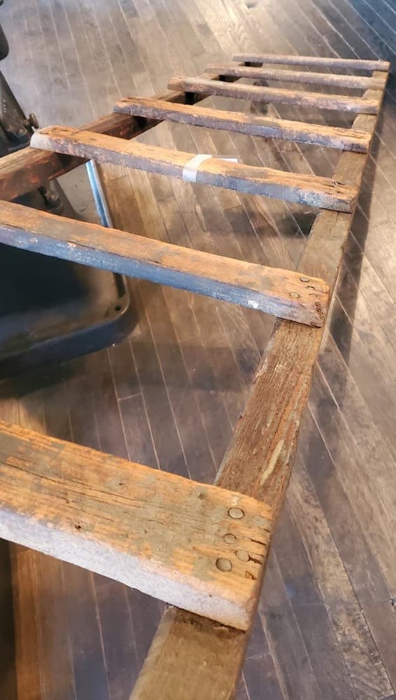
The ladder leaning on the wall was used daily by the operators to service the main shaft and their common shafts and adjust and work on the belts as required. (They were obviously smaller people than I am)
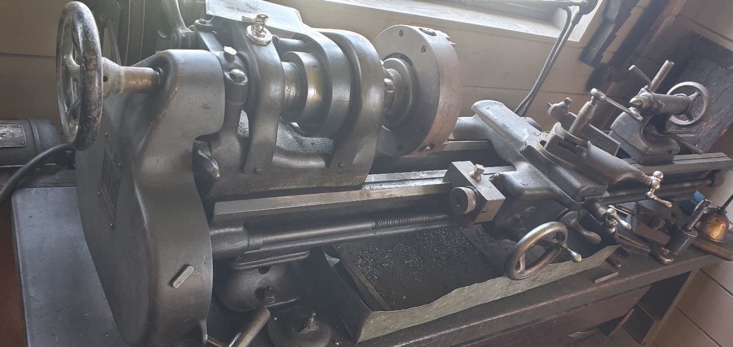
The South Bend benchtop lathe was modified to run on electricity so it could be taken off the main drive shaft to make room for other machines. This small lathe was used to do smaller, more delicate work and is still a very popular lathe today in smaller and home shops.
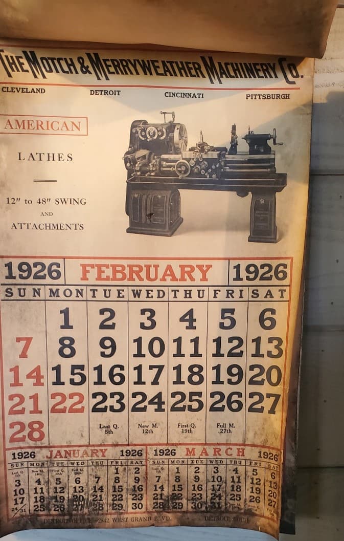
The 1926 wall calendar was hung on the wall by Frank Foriska as his first job as an employee-Fred told him to “hang it high because we’re not going to change the pages”- so today it serves as an indicator of when Frank started work here- he was 14 years old and each year he would collect chestnuts on frosty fall mornings to sell and make enough money to buy school clothes for him and his sisters. Starting ninth grade the truant officer would not allow his tardiness so he quit school and began working in Davenports Machine Shop in 1926, buying the shop in 1965, and retiring in 2000, after working here 75 years.
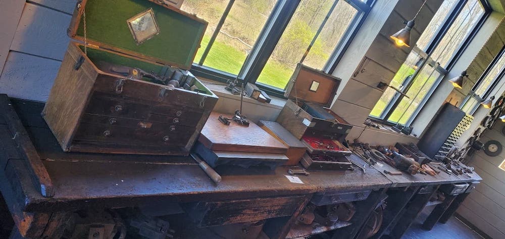
Frank’s main workbench and drawers were moved here from the Foriska shop on West College St and hold Frank’s toolboxes where he worked his whole life- on the main lathe, next to the line shafts on/off switch, and in a good position to monitor his workers.
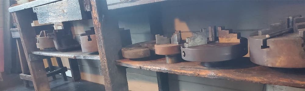
On a shelf underneath the main workbench are dozens of assorted sizes of face plates, three jaw chucks, four jaw chucks, and steady rests for use on either of the American Lathes.
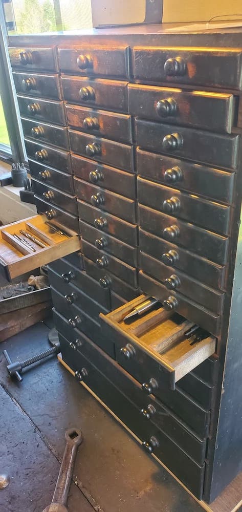
A beautiful example of days gone by is the Foriska Machine Shop wooden Drill Index. Each drawer is compartmentalized and if you look at the dividers, you’ll see that they are stamped with numbers, fractions, and letters for storage of drill bits used in our industry.
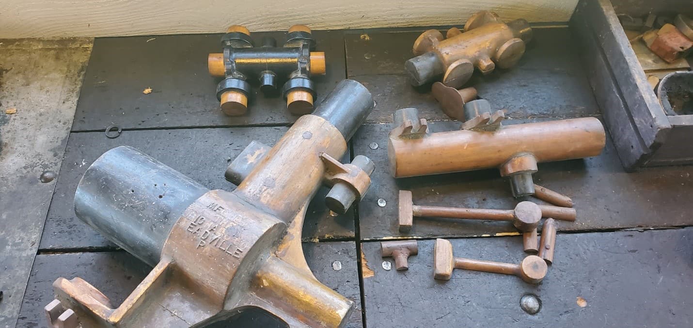
Many patterns from The Richard Co., one of Meadville’s thirteen foundries, are on display here (with more in the drawer), and they indicate the craftsmanship required by pattern makers to create all the shapes required to provide castings for machine shops to work on. Each part required split lines and fill and vent tubes in each half so the molten iron could be sand cast.
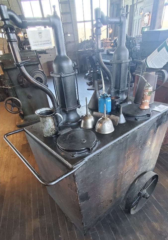
The Dual Oil tank stores the cutting oil and lubricating oil used in the shop- the operator turned the crank pump to fill his oil can, and when you release the return tube it collects the drips back into the main tank. Several oil cans, oilers and funnels are also on display.
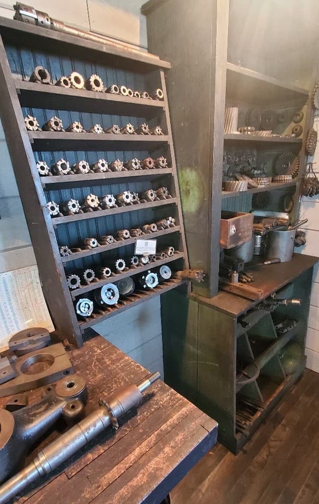
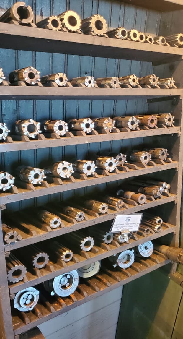
The assembly/work bench was also moved from the original Foriska building on West College St. The arbors and arbor attachments allow the Plain Mill to be converted to use horizontal cutters for machining slots and gears. The cutters for the horizontal cutting arbors are displayed in this cabinet that was also moved here from the original shop on West College Street.
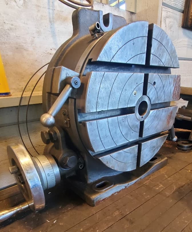
The Rotary Table attachment is used to mount a work piece to enable the operator to index his part while machining, to achieve curves, arcs, circles, angles and other assorted operations.
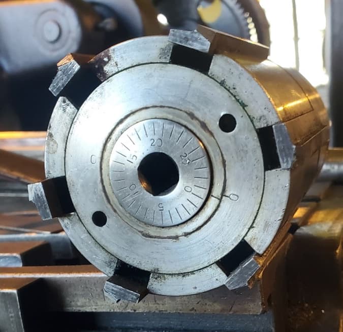
McCrosky Corporation invented replaceable blade reamers, and then began working on insertable cutters. McCrosky subcontracted this small machine shop to do their prototype work, and the insertable cutters on display here are some prototypes that Fred and Frank worked on.
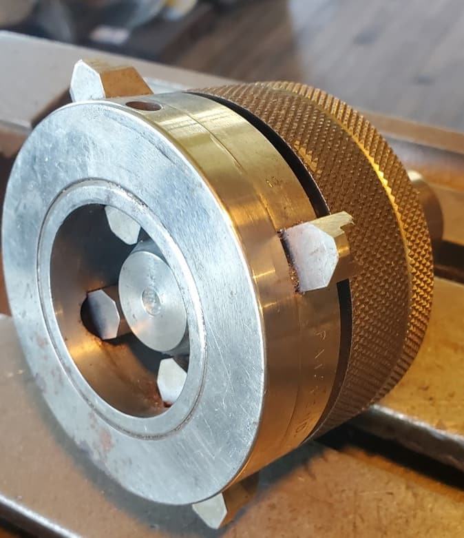
Fred Davenport developed a cone configuration inside the reamer that is adjusted by a vernier screw on the end which adjusts all the blades while keeping them parallel, as seen in the many drawings on file. On display is his patented Davenport adjustable reamer, as well as a complete set of Davenport reamers.
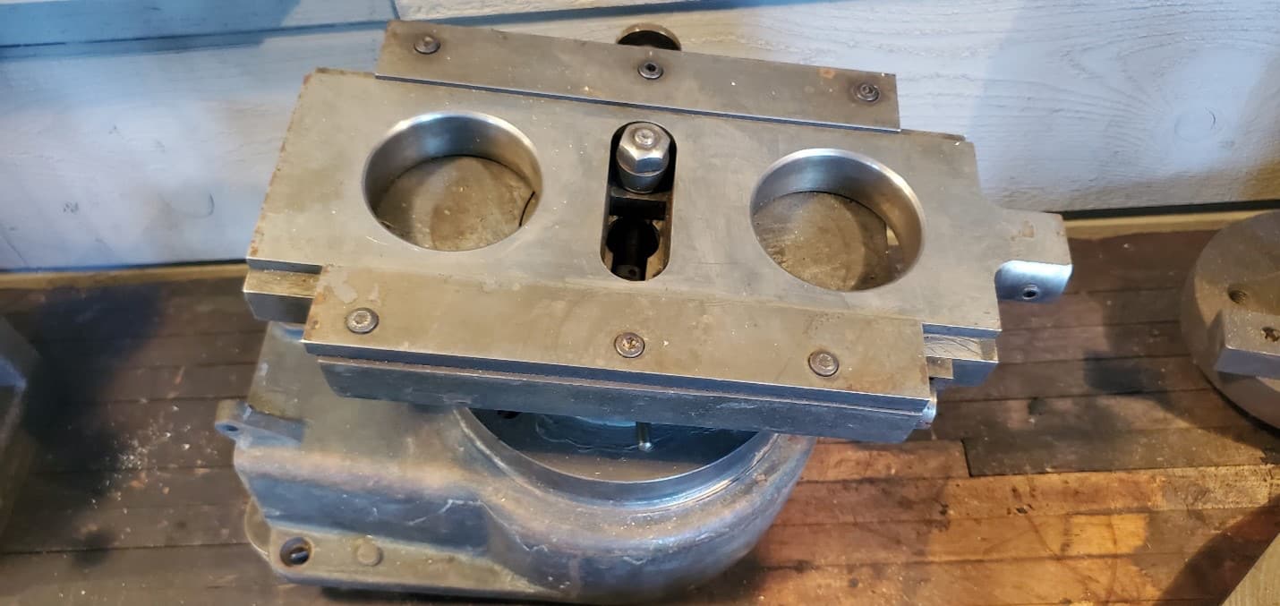
Fred also patented an adjustable boring head like this one on display which was used for mechanics to bore out the cylinders on automobile engines, and later also developed the automatic boring head attachment- the patent application drawing is on display on the drawing board in the office.
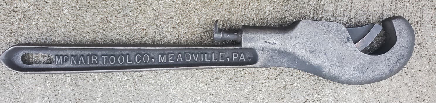
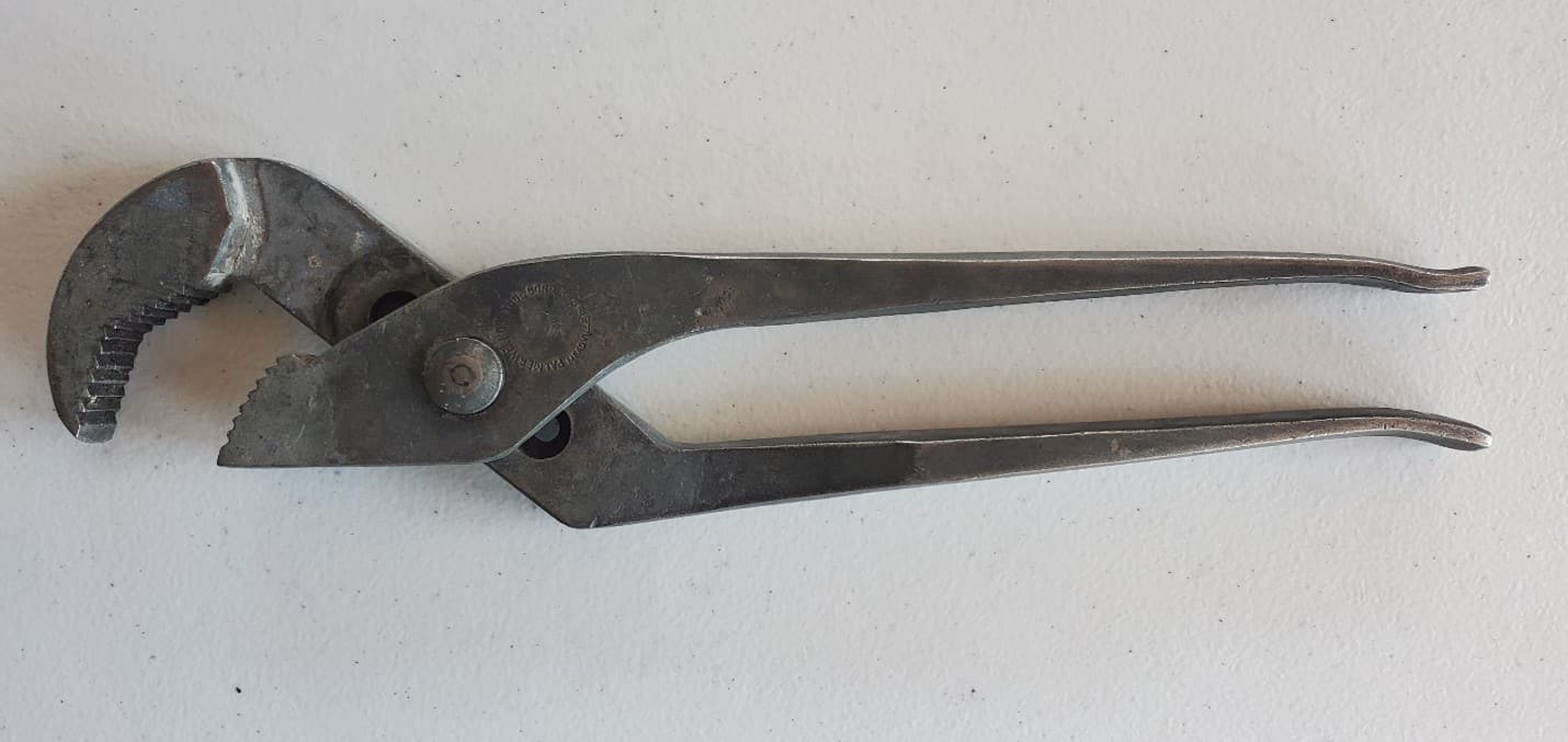
As Channellock was producing its popular adjustable wrench, other Meadville businesses also tried to capture that business. The most formidable but unsuccessful attempt was this Palmer adjustable wrench on display here.
There are three (3) Slotter attachments here and there are several drawings for these in his desk, so I believe he manufactured and sold these, but I have no further information on them.
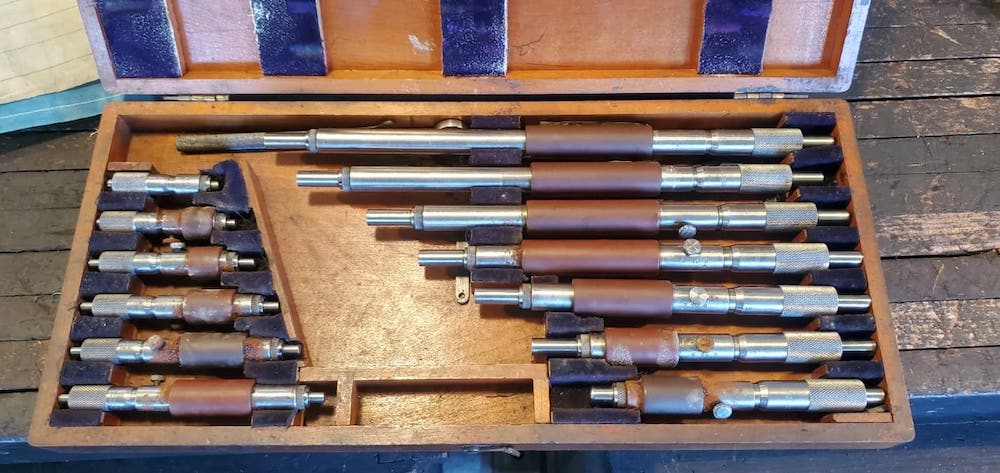
Frank Foriska’s Inside Micrometer set is in these drawers because that’s where Frank always said they belonged- so that’s where I put them.
Tap wrenches and threading dies we’re all kept on these nails in the bench back so that they were visible and readily available.
There is a spare Common Shaft Clutch assembly on the bench which allows a closer look at what is happening on the common shafts above.
Machinery’s Handbook collection- here in the museum we have a First, Second, Third and Sixth Edition of the American Machinist’s Handbook by McGraw Hill, and the Tenth, Fourteenth and Eighteenth Edition of Machinery’s Handbook by Industrial Press, who took over the publication in 1940.